Description
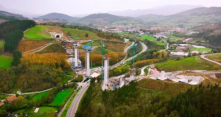
The Zumelegi viaduct is part of the high‑speed railway platform that will connect the three main cities of the Basque Country. Known as the "Basque Y" due to its geometry, it will have three lines and a central junction located at the same point. When designing the project of Zumelegi, priority was given to reusing the maximum amount of material possible and reducing on-site deadlines.
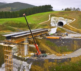
The 481 m long, structure consists of 7 spans whose distribution has allowed the simultaneous construction of a road, without interfering with traffic.
ULMA solution
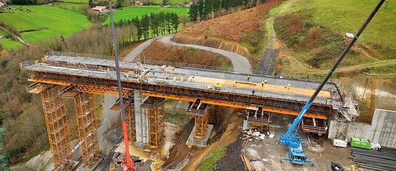
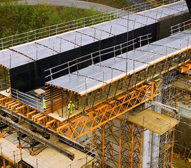
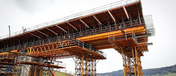
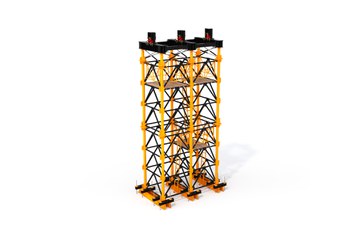
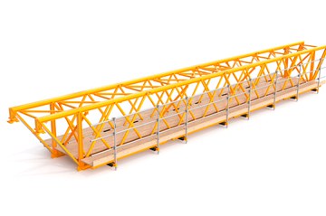
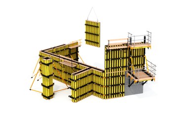
The deck has two areas with a constant edge, next to the abutments, and a central part with a variable thickness, which determined the construction method in each case. The gantry falsework has solved the abutment areas with a combination of T‑500 and OC shoring system, 6 pairs of 17.7 m long H‑33 trusses and ENKOFORM H‑120 formwork, with panels of different sizes and slopes that reproduce the section of the deck.
When designing the project, priority was given to reusing the maximum amount of material possible and reducing on-site deadlines, so after each pouring, the shoring and formwork were moved to the next pouring while the deck was shored with a single tower.
The section between pier 2 and pier 5, where pier segments start, was executed using the successive cantilever methodology.
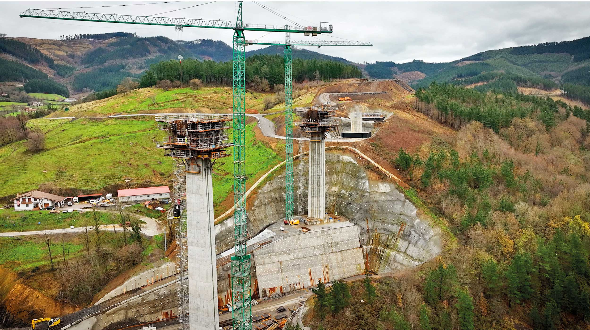
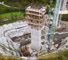
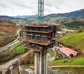
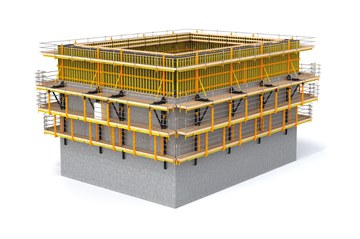
The 6 piers that make up the viaduct reach a maximum height of 71 m, so safety and performance are fundamental when selecting the equipment. The ATR self‑climbing system and the ENKOFORM V‑100 formwork panels formed a perimeter-closed assembly, which was hydraulically and autonomously lifted without depending on the crane, adapting to the change of geometry in each pour. The two interior formwork assemblies were supported on KSP telescopic platforms to absorb the variations in the geometry of the pier.
The concreting cycle consisted of 5 m pours every 3 days.
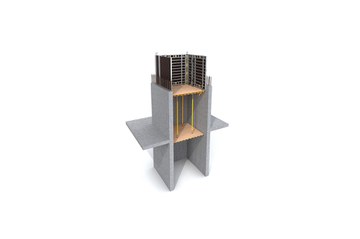
Piers 2‑3‑4‑5, on which pier segments are placed, are the beginning of the construction of the deck, using the balanced cantilever method. The main difference between them is height. The segments of piers 2 and 5 have 6.5 m high and 12 m long, while those of piers 3 and 4 have 7 m high and 12 m long. The ENKOFORM H‑120 formwork in each of the 3 concreting phases of pier segment has been adapted to the different geometries and slopes. For its assembly, support windows were created in the piers where the G bracket assembly transferred all the loads to the pier.
Project details:
- Bridge length: 481 m
- Maximum pier height: 71 m
- Segments (Pier 2-5): 12 m x 6.5 m
- Segment (Pier 3-4): 12 m x 7 m

