Description
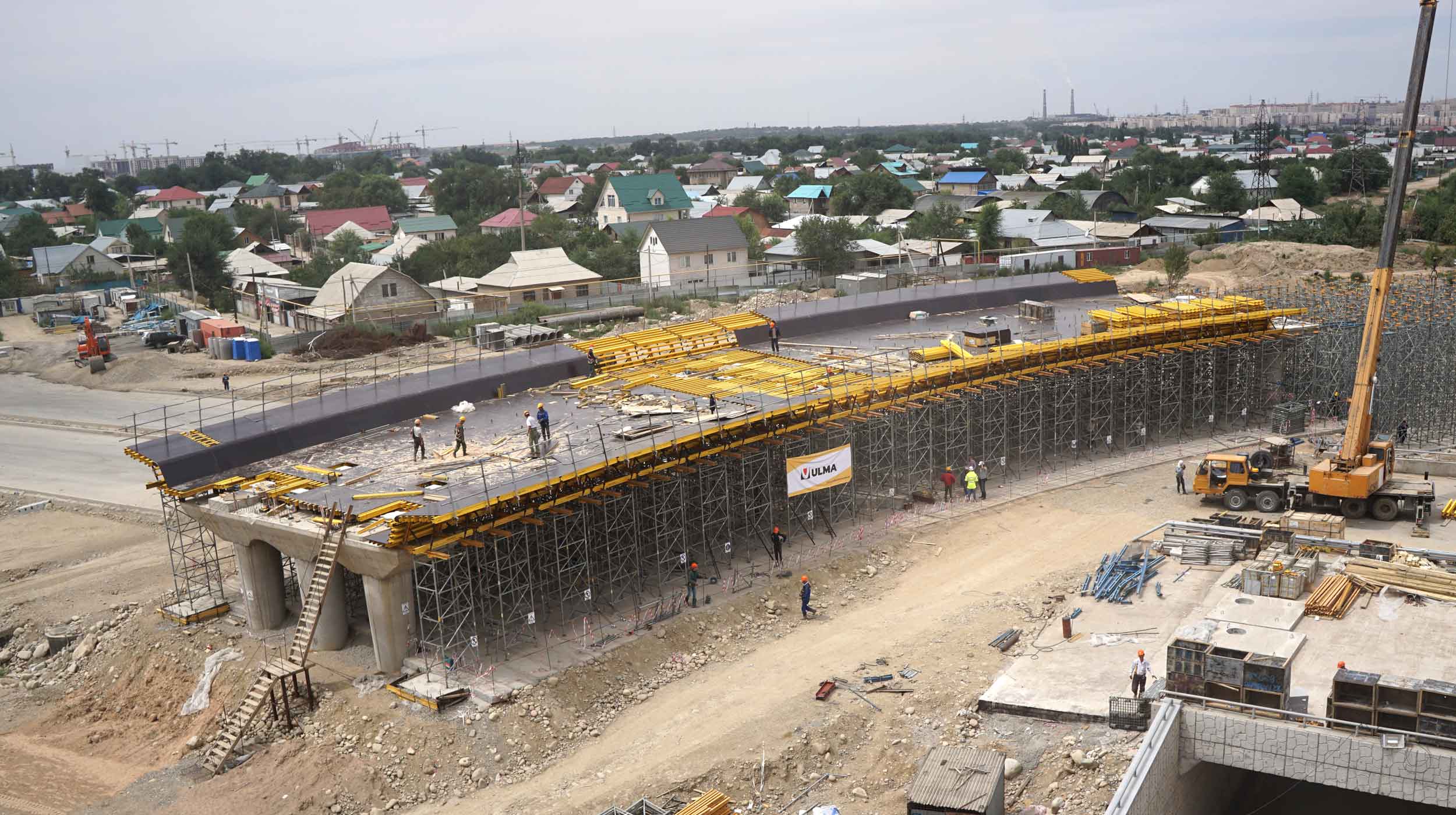
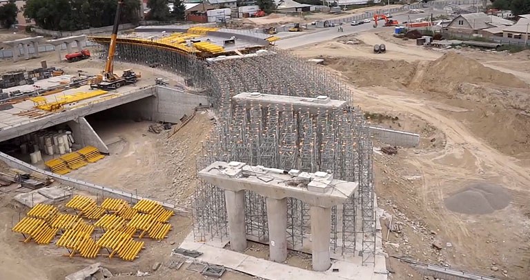
Construction of a 304.2 m long flyover at exit no. 9 over Ryskulov Street is one of 20 projects planned under the Almaty transport link network improvement programme for 2012-2018. The general contractor, BAZIS-A, entrusted ULMA Opalubka Kazakhstan with providing services for this construction project in respect of the design and delivery of formwork technology and supervision over reinforced concrete work.
Structure parameters:
- Structure width: 17.65 m
- Total structure length: 304.2 m
- Height of the load bearing structure slab: 1.5 m
- Length of the first stage between axes: 5-9 l= 121.4 m
- Length of the second stage between axes: 1-5 l=99.9 m
- Length of the third stage between axes: 9-12 l=82.9 m
ULMA Solution
The structure was designed as a flat bridge driving deck with cantilevers. Lowering the weight of the load bearing structure slab was achieved using 1.0 m in diameter hollow round channels. The contractor used foamed polystyrene cylinders as the forming component, which were submerged in concrete. Due to the differences in volume density between foamed polystyrene and the concrete mixture, significant buoyancy forces are created. After joint consultation, a special method for securing the foamed polystyrene pipes was developed. It consisted of using steel sheet brackets, encircling the foamed polystyrene cylinders in the upper section and connected with threaded rods passing through the bottom slab formwork and – via timber sheet piles – fixed to VM timber beams.
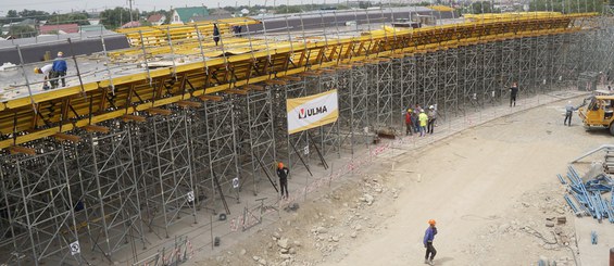
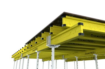
The load carrying structure was boarded in the ENKOFORM HMK system. The top grid under the slab was constructed from VM20 beams, with spans up to 30 cm, and supported on the bottom grid made of MK120 system steel beams.
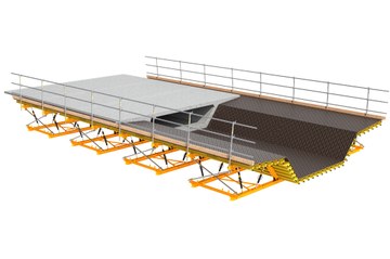
Formwork for the slab cantilevers was made of MK system steel beams, connected with system connectors and spaced with levelling uplifts (bottle screws) and forming frame systems. Connections were executed using E 20x70 pins with spring cotters. Frames, connected with HT20 timber beams using mounting brackets, formed typical 3.00m long sections and supplementary sections. Work platforms sheathed in 21 mm plywood and equipped in OSH posts and barriers were designed on both sides of the slab.

